Est. 18929.00 — 18.00

How it works

Two cars. One beautifully simple idea.

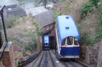
The two cars run on parallel tracks up the sandstone cliff and counterbalance one another — as one rises, the other descends. An electric winding system beneath the Top Station controls their movement through the haulage ropes.

Curious how it used to work? Explore the original water-powered railway →

HIGH TOWNTOP STATIONWINDING GEARLOW TOWNBOTTOM STATION111 FT RISE · 201 FT OF TRACKONE RISES ↑ · ONE DESCENDS ↓
The counter-balance, drawn in section
201 ft
Track length
111 ft
Vertical rise
33.52°
Gradient
3 ft 6 in
Track gauge
18
Passengers per car
5.5 tonnes
Approx. fully laden car weight

Behind the scenes

Seven parts of the railway, in the order an engineer would walk you round them. Everything essential is here in plain English — the specialist detail sits one tap away.

01

The Cars

5.5 tonnes

each car, fully laden with eighteen passengers

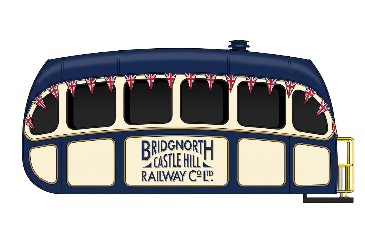
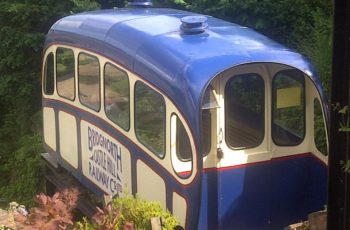
In 1955 they were replaced by aluminium monocoque cars, replacing the original wooden-bodied vehicles.
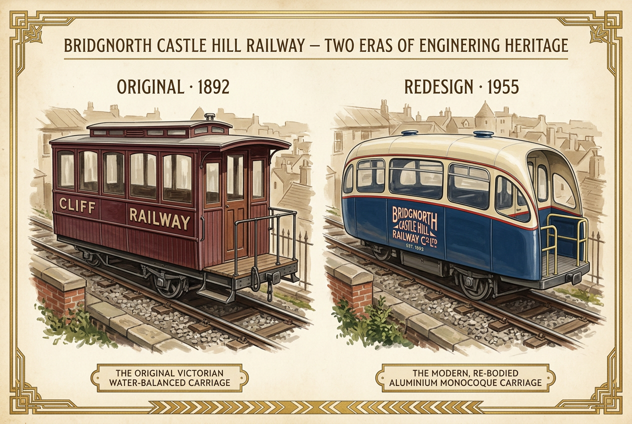
Hand-painted heritage plate showing the original 1892 wooden Cliff Railway carriage in dark red livery alongside the streamlined 1955 aluminium monocoque carriage in navy and cream.
Technical detail

The original cars were of wooden construction on a steel chassis. They were replaced with up-to-date cars of aluminium monocoque construction in 1955.

Simple sliding doors at each end of the cars still run on their original ball-bearing rollers. Each car weighs approximately 5.5 tonnes when fully laden with eighteen passengers.
02

The Track

201 ft

of double track, rising 111 ft up the cliff

A double run of rail — one for each car — climbs the sandstone cliff on a gauge of 3 ft 6 in, with concrete steps between the two tracks and rollers set into the track to carry the ropes.

Engineering the trackHeritage Art Deco diagram of the inclined track: flat-bottomed rails on timber sleepers bolted into solid rock, concrete ballast, horizontal rope rollers, and the hauling pulley on concrete buttresses at the upper station.SECTION DETAILSOLID ROCKCONCRETE BALLASTSLEEPERRAILRAILTOP STATIONBOTTOM STATIONHAULING PULLEYon concrete buttressesHORIZONTAL ROPE ROLLERSTIMBER SLEEPERS · BOLTED INTO ROCKFLAT-BOTTOMED RAILS
Technical detail

The track is 201 ft long with a rise of 111 ft, consisting of a double run of rail — one for each car — with concrete steps between. The rails are standard bull-head section of about 1972 vintage, on a gauge of 3 ft 6 in.

Original timber sleepers, which spanned the full width of both tracks, gradually rotted and were patched with a multitude of secondary fixings — allowing the rails to drift slightly out of line for a less than smooth ride. New steel sleepers set in concrete have since been inserted under the existing rails, using standard main-line spring clips. The Railway remained open throughout the eighteen-month programme.

The track rollers supporting the ropes appear to be of the original design — solid steel rollers carried each end by a ball-bearing plummer-block — with sealed roller bearings now used as replacements.

03

Winding Gear

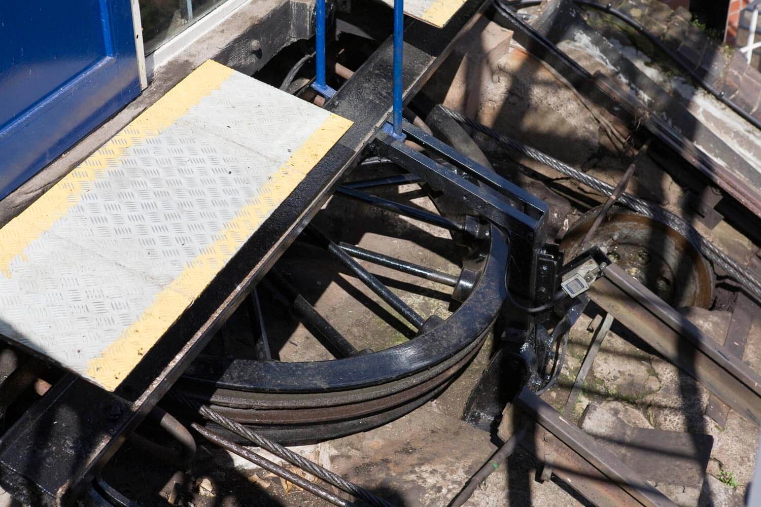
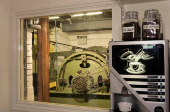
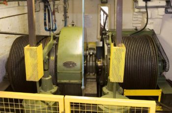
Beneath the Top Station sits winding gear of the type used in collieries, installed in 1955. The ropes wind onto two drums — one winding on as the other winds off — and three stages of reduction gearing turn a fast-spinning motor into a slow, steady pull on the drum.

650 RPM

At the motor

3 stages

Of reduction gearing

30 RPM

At the drum

The winding gear beneath the Top Station
The winding gear
The two winding drums and their steel ropes
Winding drums & ropes
Technical detail

The present winding gear is of the type used in collieries, situated below the Top Station and installed in 1955. The ropes wind on to two drums — one winding on as the other winds off. A system of three reduction gears takes the motor down from 650 rpm to 30 rpm on the drum. The final gear and winding drums are some 4 ft in diameter.

The motor itself is a 32 hp three-phase AC mining type machine, driven through a drum controller, giving a maximum car speed of 250 feet per minute.

04

Braking & Safety

No air = brakes on

The fail-safe principle

Two heavy steel weights naturally hold the brake shoes against the brake drums — the railway's resting state is stopped. Compressed air lifts those weights to release the brake, so if the air pressure ever fails, the weights simply drop and the brakes re-apply themselves.

Technical detail

A fail-safe compressed-air system operates one of the three braking systems. Two large steel weights keep brake shoes applied to the two 4 ft diameter brake drums.

Compressed air at 50–100 p.s.i. operates vertical pneumatic rams which act against the weights to release the brake. In the event of an air failure, the brakes are simply re-applied by the weights.

The speed of the cars is also regulated by air brakes acting on the haulage drums, together with proximity devices which slow the cars as they approach either end of the track. Should a rope ever break, the car's own emergency brake grips the rails until it comes to a halt.

05

Electrical Systems

Three separate electrical systems work together — one for safety, one for everyday power, and one to turn the drums.

110 V

Safety systems

Doors, indicators, overspeed switches and the dead-man's pedal.

240 V

Lighting & power

Station and car lighting, plus the radio telephone linking both stations.

415 V

Main winding motor

Three-phase supply to the 32 hp AC motor that hauls the cars.

Technical detail

110 VA low-voltage circuit runs the safety systems — the four station and carriage doors, the passenger indicators, the two overspeed switches and controllers, the dead-man's pedal and the drum winding-plate switches.

240 VA standard system supplies lighting, power and a mains-operated radio telephone linking the two stations (backed by batteries for power failure).

415 VA three-phase system drives the 32 hp AC motor through the drum controller — similar to the arrangement used on trams.

06

Driving Controls

Two indicator panels

air pressure, speed, volts, amps and door status

The driver works from two indicator panels, a single motor control handle governing both speed and direction, and a brass-handled compressed-air brake — and must stand on a floor-mounted dead-man's pedal before the car will move at all.

The Driver's Indicator PanelsTwin Art Deco control consoles with brass-rimmed gauges, indicators and levers.DRIVER · CONSOLELEFT INDICATOR PANEL050100AIR PSI0125250SPEED FT/MIN0240480VOLTMETERDOOR ADOOR BREADYTRIPRIGHT INDICATOR PANEL050100AIR PSI II-A0+AAMMETER0427TRIP INDICATORMOTORBRAKEOVERSPEEDDEADMANREVFWDMOTOR CONTROLOFFFULLAIR BRAKEDEAD-MAN PEDAL
Gauges · Indicators · Motor Handle · Brass Air-Brake
Technical detail

The driver's two indicator panels carry two air-pressure gauges, a speed indicator, a voltmeter, an ammeter, a trip indicator and various speed and door control lights.

The controls themselves consist of the motor control handle — governing both the speed and the direction of the motor — and the compressed-air brake, operated by the brass handle on the right. In addition, the driver must stand on a floor-mounted dead-man's pedal in order to start driving.

07

The Ropes

26 mm

Multi-strand steel ropes

58 tonnes

Tested breaking strain

Steel haulage rope running over a track roller
Rope & roller

There are three steel ropes: one from each car to the winding drum, and a safety rope running from one car to the other over the original winding wheel. Every rope is examined in great detail for defects every six months, and replaced every five to seven years.

Technical detail

There are three steel safety ropes — one from each car to the winding drum, and a safety rope running from one car to the other via the original winding wheel. These are 26 mm multi-strand ropes tested to an actual breaking strain of 58 tonnes. They are examined in great detail for defects every six months and are replaced every five to seven years.

From water to electricity

The Original Water-Balance System

Until 1944 the railway needed no motor at all. Each car sat on a triangular frame of steel girders housing a 2,000 gallon water tank, filled at the top from a 30,000 gallon tank on the roof of the top station. Full, the upper car weighed more than 9 tons — easily enough to counterbalance the lower car and its eighteen passengers. As the top car filled, the bottom car's tank was emptied and the water pumped straight back up to the top station tank by a pair of pumps driven by independent Forward Gas Engines. The cars were linked by a pair of steel ropes whose breaking strain was calculated at 15 times the normal working load, and were fitted with rapid gripper brakes that automatically engaged should the rate of descent become too great. A second, manually operated brake was the responsibility of the brakeman who rode on the bottom platform of each car.

The 1944 Electric Conversion

The drivers were eventually dispensed with, in favour of a hand operated brake operated from the top station, the brakes on the cars being made to operate only in the event of a rope failure. In 1943 the gas engines were reaching the end of their working life, prompting a major rebuild: the hydraulic system of counterbalanced cars was replaced with an electrically operated mining type motor of 32 hp. The haulage system consists of 2 main ropes — one winds onto the one drum as the other winds off — while a safety rope connects the 2 cars via the original head wheel. The original emergency brake was retained, so in the event of a rope break the car would grip the rails until it came to a halt. The speed of the cars was regulated by air brakes acting on the haulage drums, and proximity devices which act to slow the cars as they approach either end of the track. Further safety improvements included interlocked loading doors at top and bottom and a dead man's pedal speed controller. The conversions were carried out by Messrs. Francis & J.S. Lane, with electrical gear supplied by Metropolitan-Vickers Electrical Co. Ltd. The effect of the conversion was to double the speed of the railway, up to a maximum of 250 feet per minute. The railway reopened in December 1944 and showed an immediate increase in traffic. In 1955 the passenger cars were replaced with a more modern type, with improved lighting.

The Counter-Balance Principle
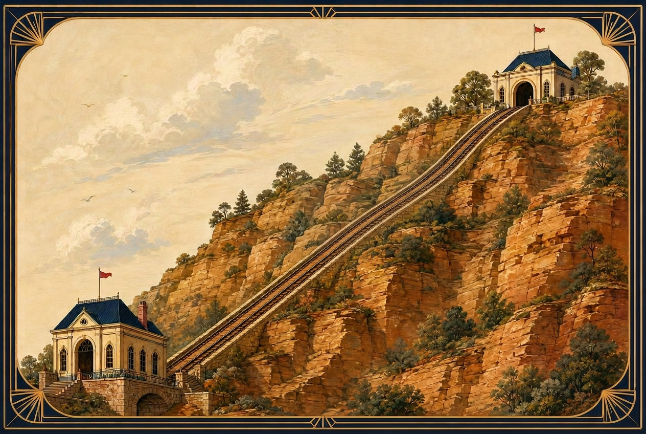
As one car ascends, the other descends. The weight of each car helps pull its twin up the cliff.
Low Town Station
Castle Hill Walk — passengers board for the climb to High Town.
The Cliff Face
The railway climbs 111 ft up the sandstone cliff between Low Town and High Town.
High Town Station
Castle Terrace — 111 ft above the river, in the heart of medieval Bridgnorth.
Gauge
3 ft 6 in
Vertical Rise
111 ft
Gradient
1 : 1.81
Track Length
201 ft
Opened
1892
The 1955 redesigned cars
The track
The track
Rope rollers & pulley